1 Abstract
Provides a description of the Exposure Time Calculator for the Flat Field Calibration Screen, both for the tunable laser and the white light source (LEDs). Includes a table of expected exposure times to meet the requirements.
2 System Description
A light projector, either a tunable laser or white light source (e.g. LED) will be used to illuminate the white calibration screen to provide the camera with a flat field calibration source. The light source will be placed in the center of the calibration screen and will reflect off of a custom made optic that delivers light back to the calibration screen mounted to the Rubin Obs. dome.
Of the following diagram, we will cover the LED and Laser+Fiber lightsource, Calibration System Optics and LSST boxes. Other elements of the calibration ETC can be found in the CBP Calibration ETC Tech Note.
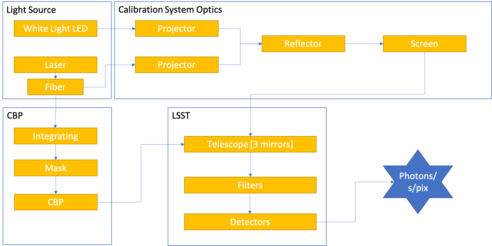
Figure 1 ETC Overview
3 Requirements
Key requirements can be found in LSE-60.
Additionally, according to TLS-REQ-0094(0096), the intensity of the white light (e.g. LED) exitance from the screen should produce a spectral radiance of 3 milli-Jansky’s per arcsec^2, as measured on the detector, with a minimum of a 5 nm bandpass.
This can be converted to spectral exitance (M) in W/m2/Hz:
where \(\lambda\) is measured in m.
To measure the required photon rate for a given wavelength:
If we assume that we want a SNR = 1000,
Filter |
Bandpass (um) |
Photon Rate (ph/pix/sec) |
Center Wavelength (nm) |
ExpTime (s) |
|
0 |
u |
0.071 |
7278.04 |
359.5 |
137.4 |
1 |
g |
0.147 |
11321.2 |
478.5 |
88.3302 |
2 |
r |
0.139 |
8241.93 |
621.5 |
121.331 |
3 |
i |
0.127 |
6202.97 |
754.5 |
161.213 |
4 |
z |
0.103 |
4365.39 |
869.5 |
229.075 |
5 |
y4 |
0.075 |
2880.52 |
959.5 |
347.159 |
For the tunable laser, besides the requirement on uniformity, TLS-REQ-0098 states that the FWHM of the luminous exitance from the calibration screen be no wider that 1 nm and be adjustable by 1 nm step size with an accuracy of 1 nm. For the purposes of this document, we will assume that requirement is met. It is also a requirement that scanning of a filter using the narrow-band light source (i.e. tunable laser) and calibration screen when stepping in 1 nm increments shall not exceed 4 hours.
We will assume a desired median SNR of 100 for all bands using the tunable laser for flat field calibration.
4 Light Source
4.1 White Light Source
- Parameters:
LEDS: The Thorlab LEDs we expect to use for each banddichroic: The dichroic we expect to use for each band.
With our white light system, we will have a unique projector for each band. For some bands we will used two LEDs combined using a dichroic. For the u and y band, we will use a single LED, but to save space they will be used with a dichroic. Only one LED will be used at a time in this case. More information can be found on Confluence.
Filter |
LED(s) |
Dichroic |
|
0 |
u |
M385L3 |
DMLP735B (Thorlabs) |
1 |
g |
M455L4, M505L4 |
DMLP490 (Thorlabs) |
2 |
r |
M565L3, M660L4 |
DMLP605 (Thorlabs) |
3 |
i |
M730L5, M780LP1 |
69904 (EO) |
4 |
z |
M850LP1, M940L3 |
DMLP900 (Thorlabs) |
5 |
y4 |
M970L4 |
DMLP735B (Thorlabs) |
For each of these LED systems, the output of the LED (as published by Thorlabs) is then multiplied by the transmission and reflection curves of the dichroic. The final irradiance from the light source is the addition of the output from each LED in the projector.
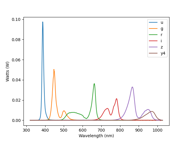
Figure 2 Output of the white light LED projector for each filter.
4.2 Tunable Laser
- Parameters:
laser_file: filename that contains the Watts/nm from the laserdecrease_expected: This is the percentage decrease from the values in thelaser_file. This should be zero if thelaser_filecontains measured levels.
We are using the Ekspla NT242 currently. It is possible that we may have a backup laser with a different output profile. Currently, we are using PGD151_NT242.txt, which is the expected levels from the distributor. We will want to update this with measured values.
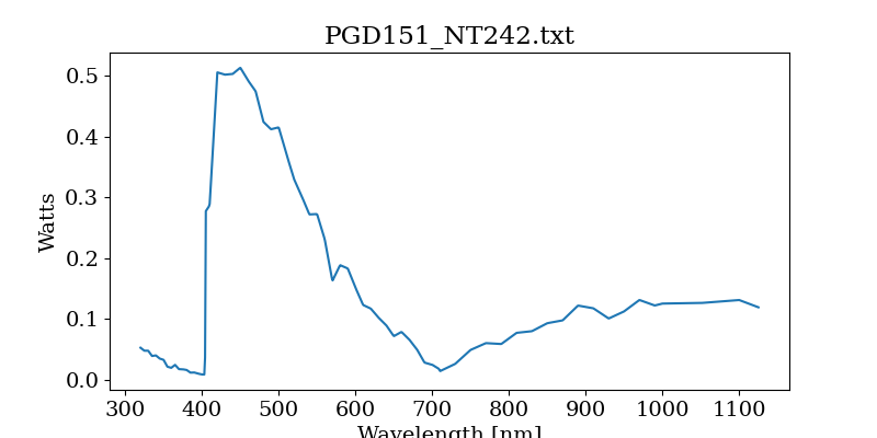
Figure 3 Output of NT242 laser
4.3 Fiber Attentuation
- Parameters:
fiber_length: Length of fiber from the laser to either the CBP or the flatfield projector.fiber_type: This is the type of ceramoptic fiber we expect to use.fiber coupling: This is the throughput decrease based on the coupling between the fiber and the laser.use_fiber: Whether or not a fiber will be used [True]
Based loosely on LTS-664, I estimate that the fiber will run ~15m from the laser to the projector.
Likely, will get this fiber from ceramoptic: https://www.ceramoptec.com/products/fibers/optran-uv-/-wf.html.
The attenuation (dB/km) for several kinds of fibers was sent to me by Ceramoptic (email) and WFNS was recommended.
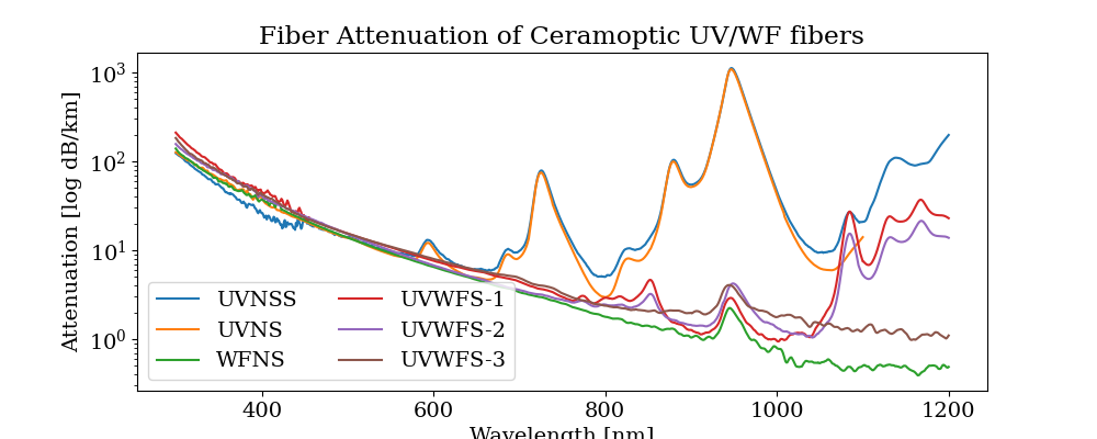
Figure 4 Attenutation of ceramoptic UV/WS fibers.
Tranmission of the fiber is then calculated:
Based on initial measurements with a NA=0.22 fiber on April 11, 2023, the fiber_coupling is estimated to be 0.8 across all wavelengths.
5 Calibration System Optics
5.1 Projector Optics
- Parameters:
system_efficiency: How much of the light that goes into the projector makes it to the camera. This can be determined in Zemax or by combinging the efficiencies of the projector and camera optics.projector_design: The optical elements that make up the projector, each having a unique coating.
The projector design is different for the white light system and the laser system. Defining the projector design is done in the ETC code by feeding a list of coatings used on different optical elements in the projector.
They system efficiency of the whole optical system is dominated by two main componentss: the central obscuration and the acceptance cone of light into the telescope. This is calculated to be 0.0113% for the LED projector and X% for the Laser Projector as calculated in Zemax for 630nm. We will assume a similar value for all wavelengths.
5.1.1 LED Projector
Design used currently uses a collimating lens followed by two converging lenses and then a field lens. The design can be found on Confluence. It requires one mirror to redirect the beam. Approximately 30% of the light leaving the LED will make it into the projector. This is difficult to measure as the LED has a output angle of 80deg. We make this estimate based on collimated LED systems available from Thorlabs.
The collimating lens used is the 1 inch Aspheric Condensor Thorlabs ACL2520U. A separate collimating lens will be used for each LED and then will be combined by the dichroic. Depending on which filter, we will use a different AR coating for this optic.
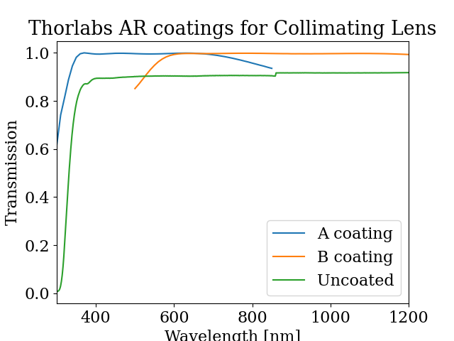
Figure 5 Transmission of AR coatings on LED collimating lens
The light will then travel through three lenses. These lenses are made of N-BK7 and must remain uncoated to work for all wavelengths. Another options is use the AB AR coating, but we are unlikely to do so.
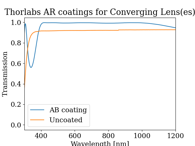
Figure 6 Transmission of coatings for converging lens.
We will also need one mirrors to redirect the light, using either Aluminum or Silver coatings. We will have to use the same mirror for all LEDs. We will likely use Aluminum (F01).
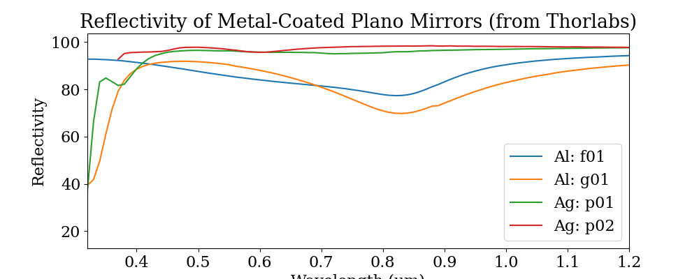
Figure 7 Reflectivity of Thorlabs mirror coatings
5.1.2 Laser Projector
For the laser projector, we will use four uncoated lenses. Two will be the Thorlabs LA4158, which are f = 250.9 mm UV Fused Silica, Uncoated lesnes. Two will be the Thorlabs LA4122 f = 40mm, N-BK7 uncoated lenses.
We expect the projector_mask_efficiency to be 87.5%, based on measurements made in the lab with a fiber with NA 0.21.
5.2 Reflector
- Parameters
reflector_reflectance: The reflective properties of the reflector
Both the LED and laser system use the “Reflector” to deliver light to the calibration screen. The diameter of the reflector is 741.3mm, with a central obscuration of 326.8mm diameter. The reflector is a custom made aspherical optic made of bare aluminum. It is currently uncoated. The Reflector should be irradiated with a f/4 light beam from the projector.

Figure 8 Typical reflective properties of aluminum
Our reflector was measured with a Minolta reflectivity sensor and the following was measured. Unfrotunately, we only have data from 44-700nm and it’s clear that aluminum will have an increase reflectivy past 850nm. We scaled the expected reflection values for bare aluminum to our measurements made with the Minolta for this final curve:
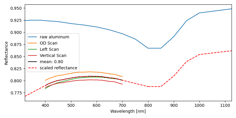
Figure 9 Measured reflectance of the Reflector
5.3 Calibration Screen
- Parameters
screen_reflectance: The reflectivity of the labsphere coating on the calibration screen.
The screen is 9.27m in diameter with a 4.18 m obscuration and is coated with Pressed Polytetrafluoroethylene Powder by Labsphere.
The screen reflectance values were taken from measurements made by LabSphere when then delivered (Collection-10467). There is quite a difference between the results from different panels. I took two reports randomly, one for the outer ring [109153-1-17] and one for the inner ring [109153-1-22], and calculated their mean reflectance.
In the future, we can possibly determine the specific reflectivity based on the location on the screen, but at this point we don’t know where the individual panels will be mounted. Therefore, I am using this mean curve to represent the whole screen.
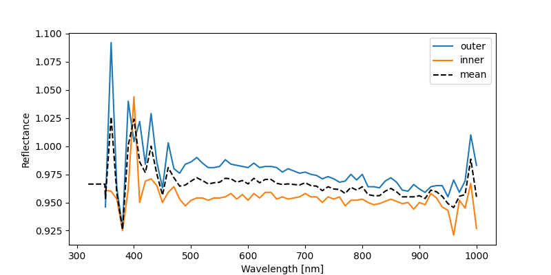
Figure 10 Reflectance of screen
The light reflected from the screen will be lambertian. Only a small angle of this light will be accepted into the telescope. According to our zemax model (Document-40906), the total system throughput is approximately 0.00025. This value should include the fraction of light accepted into the camera, but it also includes the fraction of light lost by the reflector and transmission losses due to optics and mirrors. As a conservative estimate, we define the acceptance fraction to be 0.0005. This will be refined as our zemax model is updated, and will also be calculated as a function of wavelength.
6 Telescope and Camera Throughput
- Parameters:
total_number_of_pixels: 3.2e9pixel_size: 10e-6 mf_lsst: focal length of the LSST telescope (m) [10.3]
6.1 Mirror Reflectance
- Parameters:
m1,m2,m3: Reflectance for a mirror coating; options:[Unprotected-Al,``Protected-Al``,``Protected-Ag``]
There are three mirrors [m1, m2, m3] that will be coated with either Al or Ag. The full throughput will be the combination of the three mirrors, whether all have the same coating or different. The curves we are using come from a document sent directly from Tomislav Vicuna, called Final procAg-ProcAl_bareAl.xlsx.
Currently, the understanding is that all three mirrors will be coated in Protected Silver.
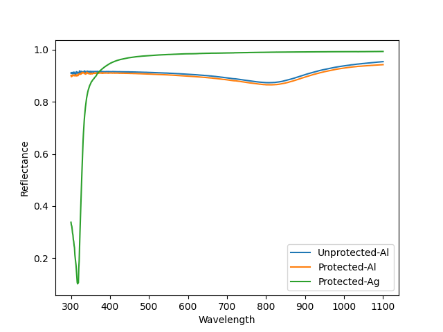
Figure 11 Reflectance of telescope mirror coatings
6.2 Filter & Corrector Throughput
Using the filter and lens throughput from the Baseline Design Throughput on Docushare.
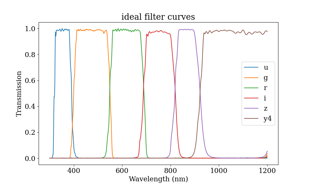
Figure 12 Ideal filter throughput
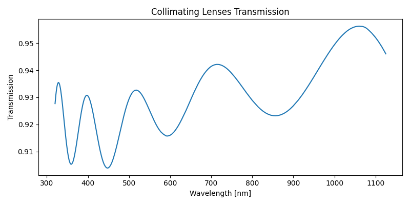
Figure 13 Total transmission of three lenses that make up the collimator.
6.3 Detector Efficiency
- Parameters:
detector_file: File with QE for the detectorPlate Scale of camera: 0.2 arcsec/pixel
Currently using the QE curve for the e2v detectors (detector_e2vPrototype.dat) from the Baseline Design Throughput on Docushare.
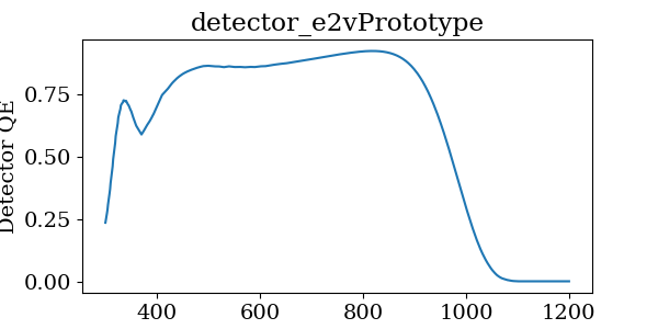
Figure 14 QE for e2v detectors
7 Readout Overheads
- Parameters:
cam_readout: readout time for LSSTCam [2 sec.]min_exptime: The minimum exposure time allowed by the camera [15 sec.]electrometer_readout: The readout time for the electrometer [not currently set]spectrograph_readout: The readout time for the spectrograph [not currently set]
The exposure time overheads are quite simplistically calculated at this time. Essentially, we can only take an exposure no more often than every 15 seconds. Therefore, if we require less than that time to reach the required SNR, the total exposure time is 13 seconds plus an additional 2 seconds of readout time.
I am not currently calculating the readout time required for the electrometer. This will have to be addressed very soon.
8 Exposure Time Calculator
The code for the ETC is currently being developed in https://github.com/lsst-sitcom/notebooks_parfa30/tree/main/python/lsst/sitcom/parfa30/exposure_time_calculator.
The exposure time calculator is saved in rubin_calib_etc.py and runs given a configuration file, like calib_etc.yaml.
First, photons per pixel are calculated, by taking the following steps:
Calculate irradiance from laser + fiber or White LIght source
Multiply by the Calibration system throughput
Calculate number of photons hitting telescope
Multiply by the telescope, filter and camera efficiency curves
Divide total photons detected by total number of pixels
Calculate exposure time for required SNR and apply readout overheads
9 Current Results
The results shown below are given when all three mirrors are coated with silver (Ag only). With our current estimates, we are meeting requirements with the LED projector. With the Monochromatic light source, we are limited by the throughput in the u-band. These results were generated with the calibration files led_ff_calib_etc_10122023.yaml and laser_ff_calib_etc_10122023.yaml.
9.1 LED
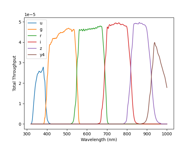
Figure 15 Total Transmission for LED Projector
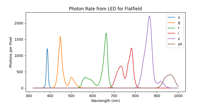
Figure 16 Photon rate for LED
Filter |
Integrated Ph Rate (Ag only) |
Exposure time (s) |
|
0 |
u |
12439.38 |
79.5 |
1 |
g |
45580.46 |
23.9 |
2 |
r |
57927.51 |
18.7 |
3 |
i |
62808.17 |
17.8 |
4 |
z |
89436.08 |
15 (minimum) |
5 |
y4 |
22409.14 |
44.4 |
9.2 Tunable Laser
With a SNR=100 at each wavelength, the total time to scan through all filters will be ~6.2 hours.
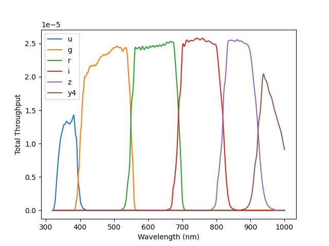
Figure 17 Total Transmission for Tunable Laser
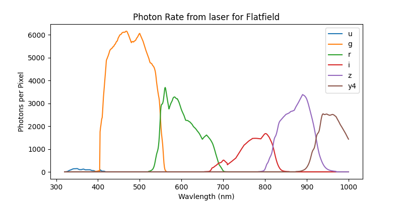
Figure 18 Photon rate for Tunable Laser
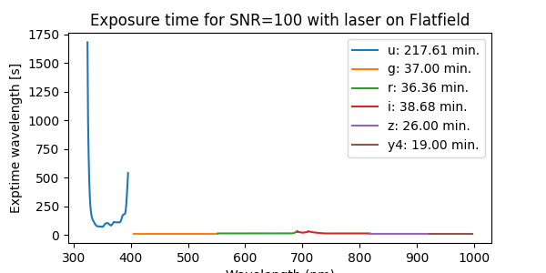
Figure 19 Total Exptime for Tunable Laser for all silver